Monday 31 October 2016

CoreXY Build - update 5

Just some minor additions today and a realisation that the new idler holders I enlarged to accomodate the new larger toothed idler bearings might be out of allignment with everything because of it. I have most of this now drawn up in 3ds Max so I'll have to go into the file and check the alignment sometime in the next few days.

New idler holder

edit:- Ok I went back into 3ds Max and adjusted the XY_Joiners so now all the idlers and Joiners should line up........................Should, because I only just started printing them :-) Looks good, in the viewport in software ;-D

I finally got around to reworking the Z axis bed holders and am a lot happier with them than the original ones. I adapted one of the remixes already uploaded to Thingiverse.

I also printed a self centering nut for the Z stepper and Threaded rod. I might go back to what I was using as a place holder as this thing doesnt seem self centering at all it wobbles! lol


Not that it really matters but these photos show the older version of the Z axis brass nut. I've since flipped it so it now points down 180 degrees and inserted into the plastic. Asthetics more than anything, it doesnt clash or crash into anything.


Added the spool holder today. This photo shows the brass Z nut refitted 180 degrees.


Printed the bowden driver housing thingy but it had to be in a different colour as I wasnt sure I had enough of the other blue left to finish it.


The last few days I've made a comedy of silly trivial errors and today thinking I didn't have any M5 x 10mm screws I drove all the way to the industrial centre to get some, completely forgetting I had a bag of them here already Face palm! The ones I had here were the kind that use a Allen key type of driver and I guess I'm happy that the new ones are Philips instead. It's also the type that a slotted screwdriver will fit, so messing about looking for the elusive Allen keys won't be an issue. ;-D

As stuff ordered from China takes ages to reach me and I'd been informed that some of the stuff wasn't available, so I was forced to order them from Aliexpress instead, then a few days later Banggood says they're on their way despite asking me what I wanted to do "Get a refund etc"
and I told them yes give me a refund. Several days later they had charged me and were shipping regardless ???? so I have a few spares on their way.

This has all caused a little confusion and I ordered some more ptfe tube not realising it was one of the items "on a slow boat from China" so even more spares....... lol. These things were like $2.00 to $5.00 so not a huge life changing problem but I'm starting to question the possiblity that I'm slowly spiralling into early onset alzheimer's lol


Sunday 30 October 2016

CoreXY Build - update 4

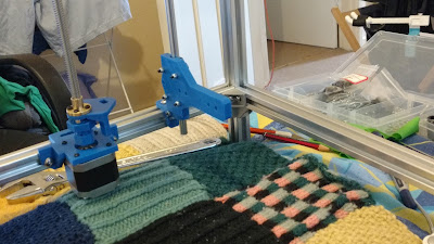
Got some more bits printed and added them to the frame for position testing.


The bottom rails will now drop down to the level of the Z stepper motor. I havent measured the final Z height that I'll be able to print, but some where between 200 amd 250 mm I think and hope.


The coupler is just a place holder for the time being and I have no idea which way the lead screw will go and if I have it upside down or not. I'll simply pick the way that gives me the most room.


I ordered 400mm acme? rod and if I have to I'll simply cut the excess off later on when the height has been established.


I think I'll be encolsing the printer with perspex eventually but because of its cost its a long way off.

I need to order some more 2020 for the print bed frame (Supplier is out of stock of course) and still havent decided on what is going to drive all this. Will it be the ramps setup as Tech2c did or something a little more exotic. My finances are screaming at me so no points for guessing the out come of this lol

edit:- On a whim I decided to back a new board that met my price range not expecting it to meet its goals...................and boy could I have been less wrong and the one I ordered will arrive sometime in January. https://www.kickstarter.com/projects/1245051645/re-arm-for-ramps-simple-32-bit-upgrade
I'll be fitting the ramps until this arrives I guess!?

I might need to buy a new power supply as well as the one I have lying around here might not be up to snuff. It had trouble reaching 12 v output last time I tried it and don't want to risk it.
edit: Apparently I threw it out, so the point is mute :-) edit:- Ordered the one posted by Tech2c BOM on Thingiverse

A few things are on order and still on their way, like the heat bed, stepper motors (The ones on here are place holders).

Next pay I need to order two more stepper motors and likely a power supply.
I still need to sort out the bowden drive as well and havent really ordered any bits for it yet. edit turns out I did actually order some bits and pieces for it.

Well I still havent finished printing for it so back to it I guess.


Saturday 29 October 2016

CoreXY Build - update 3

I had some LM8UU Bearings here but had ordered some more just to be sure and I'm amazed at the fluctuation in sizes you get with them as well as the 8mm smooth rod.

The smooth rods are all different sizes and while it's by a tiny amount when you add in the LMUU bearings you get a wide range of fittings.

The rods varied from 8.02 to 8.07 so I tried 17 of the bearings on every rod matching up each bearing to each rod to find a fit that didnt grind. I know they are cheap chinese things and should take this into account but it is still surprising me. I'm going to research the performance some of the Ingus drylin bearings.

edit:- I ordered some of the drylin bearings and boy they arent cheap I put them on the x axis but wont be able to really test them until the rest of the items I need to get this thing up and running arrive.


After clamping the bearings into their housing on the X axiz also causes them to become missaligned and to not run smoothly at all. Yikes!


I'm still waiting on some of the small nuts and bolts to arrive and am using some 35mm one I had here already to test everything.


Finally got the X Axis to run smoother. 


Wednesday 26 October 2016

CoreXY Build - update 2

Set up a stop block to cut the 2020 to length 320mm


Sitting on the bed in my flat watching TV and assembling the core xy and watching a print via octoprint. Multitasking!


I'm using toothed wheel instead of the bearings Tech2c uses so I've had to modify bits and pieces in cad/3ds Max to accommodate the different sizes.


Cutting the 400mm smooth rod down to the 320mm was awkward but used both a dremel and angle grinder to finesse the final size. I'd ordered extra smooth rods at different times and it seems one lot is a lot softer metal than the other...............go figure.


Satisfying! :-)


Stoopid camera wouldnt focus. Putting end caps I designed and printed onto the 2020 ends
STL


Managed to be one short so I had to reprint the lost one.


I'm hoping my printer will end up with the same bed dimesions as my i3 I have now. The final print bed size should be 220 x 220 x 300? plus.

As a consequence the aluminium the frame size is 380 x 320 x 300 approx but can be closer to 500 if need be.
Some of the other modifications will be 8mm X axis instead of the 10mm with bushings as I couldn't source the anodised ali for that, so I'm printing after some modifications the 8mm version available on Thingiverse.

Tech2cs build on Thingiverse

http://www.thingiverse.com/thing:1796964 The fan duct (using the if one is good three must be better philosophy) edit:- I put the origonal one back on until my new hot end shows up.

All the remixes on Thingiverse

The XY_Joiner for 8mm rods on X-Gantry I've modified mine to use the toothed idler bearings I'm using. You can see them in some of the photos above, but here's some close ups.

They measure:- inside diameter 12mm outside 18mm are 10mm thick and have a 3mm centre hole.


edit:- I had to change the x axis plastic bits to accomodate the new idler bearings
X_Carriage.stl


Tuesday 25 October 2016

Core XY Build - update 1

Cutting some of the 2020 aluminum to 380mm 4 at a time so they're the same lenght. At last some kilojoule burning exercise lol

I've already cut the uprights at 500mm and tomorrow I'll be cutting the 4 x 320mm
Mine will be a little larger so the build plate is 220 x 220 x 300+ mm

Build your own corexy, follow along with Tech2c's build here and here


Saturday 15 October 2016

White vs Glow in the dark Blue pla

This follows on from the previous post.

Same file so same temps etc the white is having serious problems with banding. Cooling...maybe!


but the glow in the dark blue is printing really well in comparison


The GITD was a little stringy but that seems to be its nature. I've adjusted the retraction etc for another red I have here and its doesn't suffer the same issues. The Glow is the worse with the white following behind it in the stringing stakes.


Arrived at the crossroads...........now what?

Ever feel like you'd be better off sitting naked in the middle of the snowy river during winter and hitting your family jewels with a flat rock because it would feel better than pursuing a print?

lol me either..... but I can see it from here.

If it could go wrong it has!
* Brittle filament

* The recess that holds the neck seems like it's grown wider and the neck flops around like a Richard in a gumboot where as the previous print it slid into a tight fit even without the bolts. The neck joint works as a neck should it just doesn't slide in like it did before before bolting it down.

* I had to counter sink for the thicker neck shelf so the bolts I have here would fit and that was a -messy and ugly exercise. I didn't want to buy longer bolts as the next design will take all these issues into account. Note that the 4 screws with washers are more than enough to hold the neck.

* The old neck I'd left still strung up on the old uke and it now has a permanent upward bow which means even if the neck housing is strong enough the neck is too weak to take the tension of the strings.

So I'm in two or more minds here, give up or back to cad for another redesign. (I'm so sick of this thing!)

A move to plain white pla which has been presenting with its own issues on the roll(s) I have here lately, but might prove stronger than the glow in the dark pla I'm using now.

Do I make a wooden neck which is what I was going to do originally but changed so others can print it? It would be stronger and I have some thoughts on using rectangular bar to be set into the neck instead of the carbon fibre tube. Something that is used in luthiery often with timber necks needing support but not adjustment with a truss rod. More carbon fibre but solid not hollow?

-----------------------------------------------------------------------------------------------------------------------


I used a dowel locator, I only have one 6mm one :-) to transfer the hole layout to the new body. I originally just used a transfer punch type of  method before because the fretboard wasn't glued on.

I was reluctant to model all the holes in Max before but now I have the thicker neck shelf and not wanting to buy more/longer bolts, should I just model the counter sink to accommodate the shorter bolts or just buy longer bolts?


I've highlighted the small nearly invisible pin prick the dowel pin made with a pencil


The reason we have the word fugly in our word keeping thingy. Despite its looks it's a tight strong joint, just ugly.

Brittle filament just shattered by the only bit I had that was the right size a spade bit :-)

Looks worse in person but the relief is too much and more of a bow.

The nut end and heel end are proud, meaning for this to even start to work some neck angle would be needed even if it wasn't going to bend even more under tension.


Grown wider buy 2 to 3 mm somehow............or the neck shrunk or both.


I'm currently reprinting another thing, in glow in the dark pla to compare it to the white one I printed yesterday.
The white is making my printer look like it has a bent z axis or lose belts as it comes out with bad banding. It could also be the cooling as I added the new silicone boot for the e3d hot end and the fan duct doesn't point where it did before and the white could be very dependent on cooling. 

This change doesn't seem to affect other colours, so it might just be the white after all, being very finicky about cooling. Hence, the need for the reprint to show the difference and set my mind at rest that it isn't the faults most people would swear it was. I've see the white do this before and also want to reassure myself it isn't the light reflecting differently off it compared to other type or colours of filament.

The white is still good for structural things that don't need to look good, but you wouldn't rely on it for a nice finish.

So if I'm reprinting in white I'll need to source some more that might not suffer from this issue,
and if I'm going back into cad adding and correcting things then I should separate the ribs and use a shell modifier on them to thicken them up a bit more so they're not so skinny and susceptible to breaking.

3ds Max's shell modifier adds thickness to anything it is applied to, (you can make things skinny as well by adding it to the inside)

A combination of a different filament and thicker ribs will help the infill support more area so they're not so susceptible to breaking,.............he said obviously trying  to convince himself it is the solution he's desperately looking for. :-)
I'll also need to research carbon fibre solid stock say 3-4 mm thick 12 - 15 mm wide and whatever suits the neck length. Do I add two or three side by side.

Something like this
My brain hurts lol


Friday 14 October 2016

Gratuitous shower scene

Ok I've glued on all the broken pieces that I didn't lose lol and I had a small can of automotive clear acrylic lacquer and blasted what was left in the can on the skeleton print. I did this in the sad hope it will help strengthen the printed filament or be like an old rusted car where the only thing holding it all together is the paint.

I'm pretty confident that this one will be strong enough (famous last words) that it will not cause the neck to warp. The neck I'll be using is the one from the previous print so it will probably bend but I'm hoping only enough to allow some relief on the fretboard (Who's he think he's kidding ) :-) If it bends too much then back into 3ds Max to make it thicker and make pockets for 3x6mm carbon fibre tubes rather than the setup I have now which is 1x6 mm and 2x4 mm square tubes.


Hanging in the shower to dry and de fume. I've yet to blend the glued joints with some heat so it will look a little better after this but I will leave it to last after I've fitted the neck and bridge and pickup.


.......and just in case you dropped in here wondering what the @#$% I am doing, then this is the goal. 

This one was really weak in the body where the neck was bolted on and caused the neck to bend under the pressure of the strings.


The fretboard was a cheap Chinese one I got all ready to go all fretted up etc. If I'm forced to reprint the neck then I might make my own fretboard if I have enough ukulele fret wire here. The skinny arse wire they've used can only just handle one fret level and crown and I doubt it will put up with a second go around with a diamond plate and file.


OMG The humanity!

I've been breaking ribs all day, this is ridiculous. The filament seems really fragile compared to the last batch I used.

It hard to say if this is a temperature thing and layer bonding is an issue or if its just a brittle batch. Still nothing much to do about it other than try and be more careful I guess. I can always comb over the growing bald patches in my hair lol

The print looks nice so it's not all bad despite the stringiness that was cleaned up with the heat gun. Managed to nearly melt the thing staying too long in one place though :-D.


I'll be using heated metal push bike tyre changers I have to help blend the joins, along with the soldering iron. They have a spoon shape to them which lends them to blending and smoothing the joins.


Monday 10 October 2016

More broken ribs

I successfully printed the file that failed the other day. I did break some of the ribs about 5 times trying to remove the supports lol.

Getting the supports out from the pickup/jack hole was tedious and slow but got there in the end. Gluing the ribs back on was difficult and they don't end up sitting in the same location they were and don't sit down flat on the surface properly, but the same happened to the first one I printed and I managed to get them together....eventually.


Stringing seems worse on this despite the same settings, there's no keeping this filament happy I think. :-)


So many broken ribs on the second print. These were just broken and I don't know why, not that I care any more I just want this done lol I'm going to glue these back on after the main body is glued together.


Third print. I changed the supports again and it worked well but I had some trouble getting them off, it was slow going but got there in the end.


Bought a cheap heat gun today despite not really having the money as the stringing on this filament seems unstoppable. Its not really bad just annoying not being able to fix it with temps and retraction. I prayed to the household 3d printing gods but they were useless lol


Ok this one rolled off the production line sometime early in the morning, it even didn't end up with inexplicably broken ribs either..............but

Started at 9am finished sometime before 7am the next day!


The stringing was still there! 


It's a very delicate type of stringing and the new heat gun will take care of it.............now to try to remove it from the pei and to see how many of the ribs I'll break along the way :-) Nice layers going on as well happy with most of these settings.......so far.