I'd just bought some more paint from a local Aldi on a whim and had finally gotten around to fixing the blown capacitor on my compressor.

Here's the first idea I was working on that used the spare perspex. My mistake was, and would have been easily fixed, had I continued on with it, would have just been to make the 3d printed top a lot thicker so it didn't flop down and bow.
This disappointed me, but that's what you get when you're prototyping, and trying to save on filament use, I guess.
Polyalchemy Elixir pla Orange from https://www.phaser3d.com/


Not a bad idea and it fulfilled the criteria as a paint caddy I guess, but it wasn't giving me that excited "I'm on to something here" feeling, so I tried something different.


Despite using a larger nozzle on my 3d printer, It still used a lot of filament and still wasn't exciting me, So I thought about using the empty spools of filament that everyone who 3d prints, has lying around. Throwing out plastic has always concerned me!

I found an empty roll from a now sadly out of business, and used a number of tools to drill holes into what I decided was going to be the top of the spool when laying down on its side.
This then got me thinking and the possibilities and excitement began
It occurred to me that with as many small bottles of paint I now have, I would be wanting to make a few of these and since I usually use pretty much one brand of filament these days
https://3dfillies.com
I focused on this one brand
I would need a way to join a few of these spools together and then I got kind of side tracked,
Compliant Mechanisms had just mad e splash on the scene and had me hooked.
The idea that I might be able to use a compliant mechanism to join two of these rolls together along with a carrying capability to allow the centre of balance to work to my advantage.
After the usual hours of drawings to get my head around the concept I settled on three designs to try.


The idea was that the prong would be spring loaded? ganged into threes and push into the hole in the centre of the spool. A hook and eyelet would be screwed into each end so they could be chained together. This would allow you to carry and not tip or spill any of the bottles in the caddy.
After a lot of test prints, I decided that I'd indulged my idea for way too long and went back to an earlier idea I had brushed off, to indulge my Compliant Mech designs.
I then looked at ways to drill the holes to accommodate the paint tubes and this is going to depend on your brand of paint, or whatever it is you want to store, and the size of the bottles.
I looked at three way to make the holes, but this depended on what I had, that was even close to the sizes I needed.
1. Hole saw kit i have.
2. Forstner bit
3. Christmas tree bit also called a stepped bit


While I settled on a hole saw it was mainly because I had one size that suited both my bottle sizes. I would certainly suggest a stepped bit if you can find one with a good range of sizes and practice learning how to set the stopping point, if you aren't going all the way through with one.

It was about now that I realised this would probably work really well as an idea and it dawned on me that I had only one of the clear spools, and decided to make this exclusively for the 3d Fillies spools because I have so many that are nearly empty now.
This decision now dictates all my measurements from this point. You would need to modify the files I will eventually upload to do this for another sized spool or just copy the design idea.
I got out an empty black Fillies spool and using a heat gun easily removed all of the labels.

First off, I used my caliper to find the right sizes of the spool and committed it to paper.

Then off into Fusion 360 to model up the spool which I can no longer find in the fusion cloud lol I do think I might have it exported and saved on my laptop but I've yet to check that. edit yep got it phew! :-)
I got another 2 holes in the design and went from 8 on the clear spool to 10 on the black.
You could, if you're able to use a pedestal drill and some wooden supports, be able to fit in more at this size or smaller if you are careful and have done this kind of thing before.

Then I took a screen shot of the face of the hole pattern and brought it into Affinity Photo, my photoshop equivalent and scaled it up to the size of the actually roll.

Then I used a light spray of some adhesive I have, to coat the back of the paper after printing it out, and stuck it lightly to the spool.
I then used an awl to poke some holes in the centre of each hole that needed drilling then using a small stepped drill bit I made some small pilot holes for my hole-saw to be guided by.
I drilled all the holes then cleaned up the sharp edges left behind with my de-burring tool.


Now back into Fusion to design the turntable part of this design.
The thread that make this modular are a real pain and causing me no end of trouble as they need to be customised to suit the diameters I'm needing.

I then looked at ways to drill the holes to accommodate the paint tubes and this is going to depend on your brand of paint, or whatever it is you want to store, and the size of the bottles.
I looked at three way to make the holes, but this depended on what I had, that was even close to the sizes I needed.
1. Hole saw kit i have.
2. Forstner bit
3. Christmas tree bit also called a stepped bit


While I settled on a hole saw it was mainly because I had one size that suited both my bottle sizes. I would certainly suggest a stepped bit if you can find one with a good range of sizes and practice learning how to set the stopping point, if you aren't going all the way through with one.


It was about now that I realised this would probably work really well as an idea and it dawned on me that I had only one of the clear spools, and decided to make this exclusively for the 3d Fillies spools because I have so many that are nearly empty now.
This decision now dictates all my measurements from this point. You would need to modify the files I will eventually upload to do this for another sized spool or just copy the design idea.
I got out an empty black Fillies spool and using a heat gun easily removed all of the labels.


Then off into Fusion 360 to model up the spool which I can no longer find in the fusion cloud lol I do think I might have it exported and saved on my laptop but I've yet to check that. edit yep got it phew! :-)
I got another 2 holes in the design and went from 8 on the clear spool to 10 on the black.
You could, if you're able to use a pedestal drill and some wooden supports, be able to fit in more at this size or smaller if you are careful and have done this kind of thing before.

Then I took a screen shot of the face of the hole pattern and brought it into Affinity Photo, my photoshop equivalent and scaled it up to the size of the actually roll.

Then I used a light spray of some adhesive I have, to coat the back of the paper after printing it out, and stuck it lightly to the spool.
I then used an awl to poke some holes in the centre of each hole that needed drilling then using a small stepped drill bit I made some small pilot holes for my hole-saw to be guided by.
I drilled all the holes then cleaned up the sharp edges left behind with my de-burring tool.


Now back into Fusion to design the turntable part of this design.
The thread that make this modular are a real pain and causing me no end of trouble as they need to be customised to suit the diameters I'm needing.


The spool sits about 15mm above the base and only extends to the depth-extent of the spool and this is where the first thread is.
The yellow print in this is the second stage, and has two threads, male and female to which the base and the top, or another section, if needed is screwed on before adding the top which will also have a small handle.

Purple PLA https://3dfillies.com/plasilk-filament-175mm-1kg

Yellow filament is some old Blueprinted pla I had. I tried searching for their new name and address but nothing is coming up so I'm assuming they're closed down now


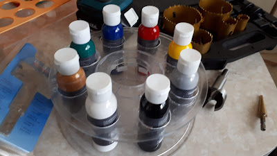
Both spools spin beautifully and I do have some video but its too large to upload. (Read as lazy)
I've now designed and am ready to print the top which has a handle but I'm still reprinting the main section (Yellow in photos) that would be the one reprinted if you wanted to stack more spools.
I sorted out the threads and they now work without a lot of sanding etc.
I realised you could get to the lower spools contents by simply lifting the top spool doh! This means that the 80mm gap I left between spools could be lowered .... I haven't checked by how much yet though.
You could use the top handle print just on the one spool as all the threads are the same.
I looked quickly at other paint bottles available and found that many of them are even smaller and some kind of mods would be needed to accommodate them or simply dedicate a single modified spool to the smaller bottles. Still a bit of work to go.
-------------------------------------------------------------------------------------------------------
Here are some fantastic Australian airbrush paints that will go on a wide range of surfaces and take a wide range of clear coats.
https://www.airbrushasylum.com.au/store/c69/Trident_Colours.html
More information on the Trident range of airbrush paint.
https://youtu.be/VJbK8B8btos
_____________________________________________________________
Needless to say you could make this to suit anything and not just airbrush paint :-D


Added another layer :-) Found out you could store or use to feed filament to a printer lol
If you go higher I'd increase the size of the base inside the fusion file from the 130mm to say 200mm
NOTE: This is still a WIP and the files are subject to change on a whim!!!
Attribution Open Source as usual.
Here are the files for you to play with if you got this far.
https://www.dropbox.com/s/xygkk7tbsh1k5zt/Airbrush%20Tray.zip?dl=0
Attribution Open Source as usual.
Here are the files for you to play with if you got this far.
https://www.dropbox.com/s/xygkk7tbsh1k5zt/Airbrush%20Tray.zip?dl=0
The duality of this design
Using just the base and a spool you can also turn this into an airbrushing turntable for small to medium sized items.
This video is showing them being turned into a turntable for some air brushing. More work would be needed, like attaching something to either side like a circle of mdf and screwed to stop it from coming off. I'm thinking 6mm mdf not the 12mm I show here. But that would be up to you.


